Basics of IP Addressing and the OSI Model

Basics of IP Addressing
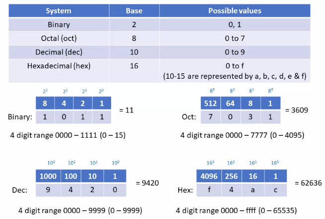
IP Addressing – The Basics of Binary
IP Address Structure and Network Classes
IP Protocol
- IPv4 is a 32 bits address divided into four octets.
- From 0.0.0.0 to 255.255.255.255
IPv4 has 4,294,967,296 possible addresses in its address space.
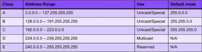
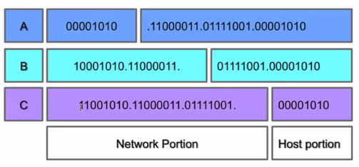
Classful Addressing
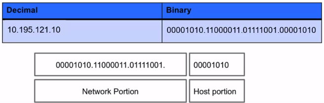
When the Internet’s address structure was originally defined, every unicast IP address had a network portion, to identify the network on which the interface using the IP address was to be found, and a host portion, used to identify the particular host on the network given in the network portion.
The partitioning of the address space involved five classes. Each class represented a different trade-off in the number of bits of a 32-bit IPv4 address devoted to the network numbers vs. the number of bits devoted to the host number.
IP Protocol and Traffic Routing
IP Protocol (Internet Protocol)
- Layer 3 devices use the IP address to identify the destination of the traffic, also devices like stateful firewalls use it to identify where traffic has come from.
- IP addresses are represented in quad dotted notation, for example, 10.195.121.10.
- Each of the numbers is a non-negative integer from 0 to 255 and represents one-quarter of the whole IP address.
- A routable protocol is a protocol whose packets may leave your network, pass through your router, and be delivered to a remote network.
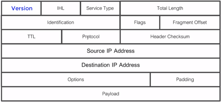
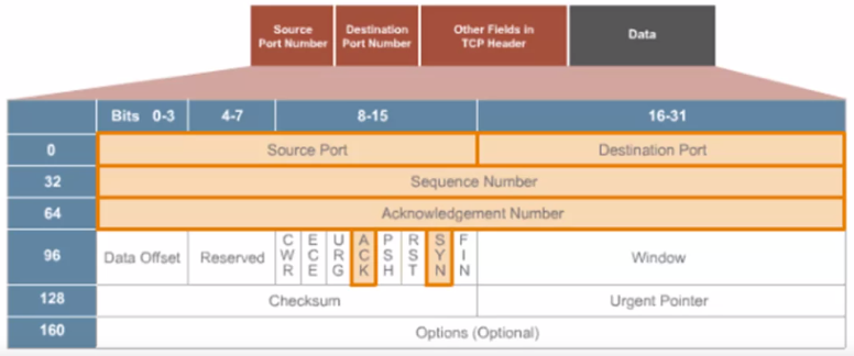
IP Protocol Header
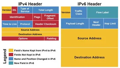
IPv4 vs. IPv6 Header
Network Mask
- The subnet mask is an assignment of bits used by a host or router to determine how the network and subnetwork information is partitioned from the host information in a corresponding IP address.
- It is possible to use a shorthand format for expressing masks that simply gives the number of contiguous 1 bit in the mask (starting from the left). This format is now the most common format and is sometimes called the prefix length.
- The number of bits occupied by the network portion.
- Masks are used by routers and hosts to determine where the network/subnetwork portion of an IP address ends and the host part starts.
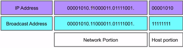
Broadcast Addresses
In each IPv4 subnet, a special address is reserved to be the subnet broadcast address. The subnet broadcast address is formed by setting the network/subnet portion of an IPv4 address to the appropriate value and all the bits in the Host portion to 1.
Introduction to the IPv6 Address Schema
IPv4 vs. IPv6
In IPv6, addresses are 128 bits in length, four times larger than IPv4 addresses.
An IPv6 address will no longer use four octets. The IPv6 address is divided into eight hexadecimal values (16 bits each) that are separated by a colon(:) as shown in the following examples: 65b3:b834:54a3:0000:0000:534e:0234:5332 The IPv6 address isn’t case-sensitive, and you don’t need to specify leading zeros in the address. Also, you can use a double colon(::) instead of a group of consecutive zeros when writing out the address.
0:0:0:0:0:0:0:1
::1
IPv4 Addressing Schemas
- Unicast: Send information to one system. With the IP protocol, this is accomplished by sending data to the IP address of the intended destination system.
- Broadcast: Sends information to all systems on the network. Data that is destined for all systems is sent by using the broadcast address for the network. An example of a broadcast address for a network is 192.168.2.2555. The broadcast address is determined by setting all hosts bits to 1 and then converting the octet to a decimal number.
- Multicast: Sends information to a selected group of systems. Typically, this is accomplished by having the systems subscribe to a multicast address. Any data that is sent to the multicast address is then received by all systems subscribed to the address. Most multicast addresses start with 224.×.y.z and are considered class D addresses.
IPv6 Addressing Schemas
- Unicast: A unicast address is used for one-on-one communication.
- Multicast: A multicast address is used to send data to multiple systems at one time.
- Anycast: Refers to a group of systems providing a service.
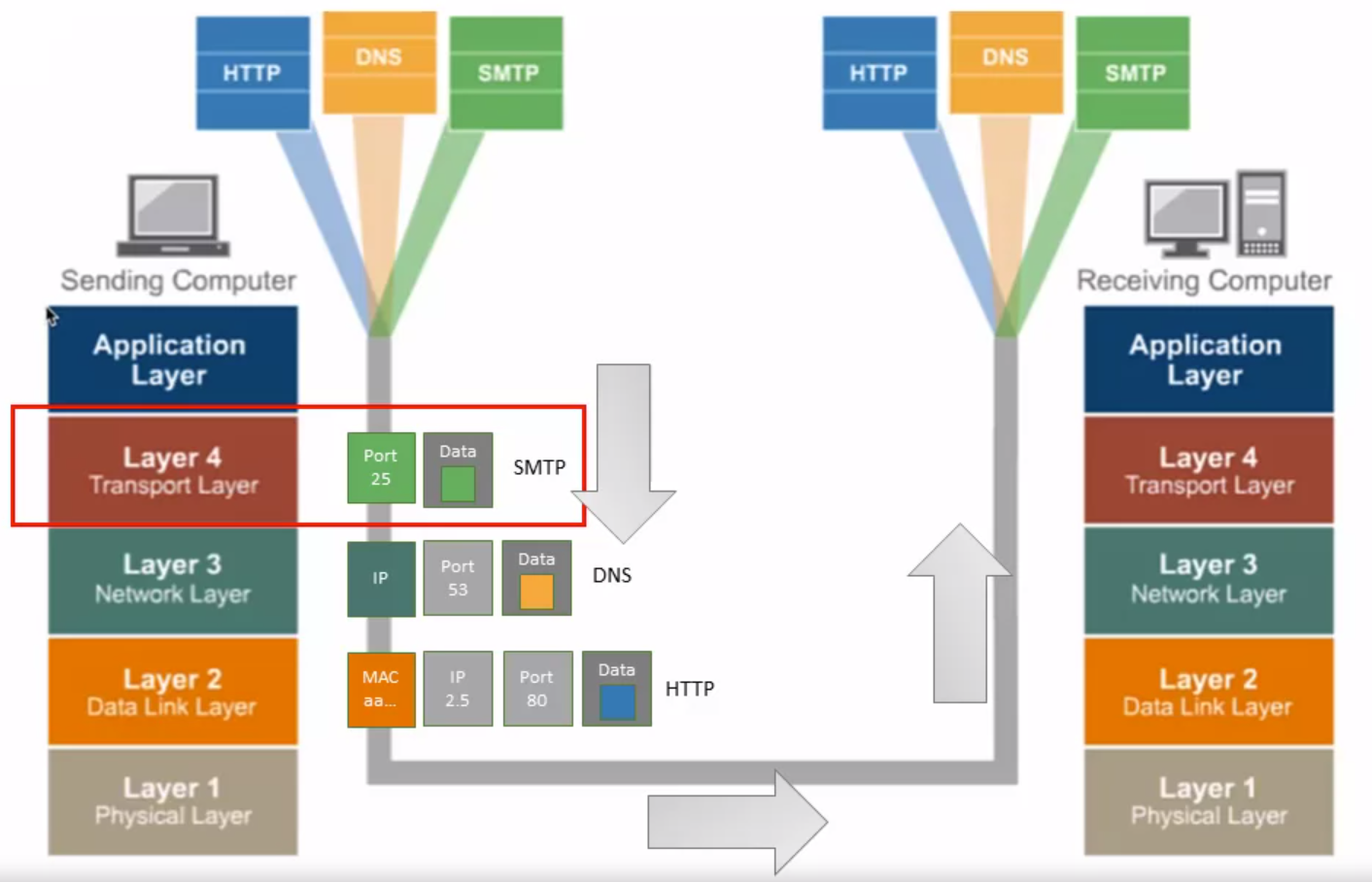
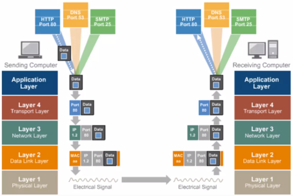
TCP/IP Layer 4 – Transport Layer Overview
Application and Transport Protocols – UDP and TCP
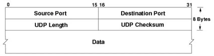
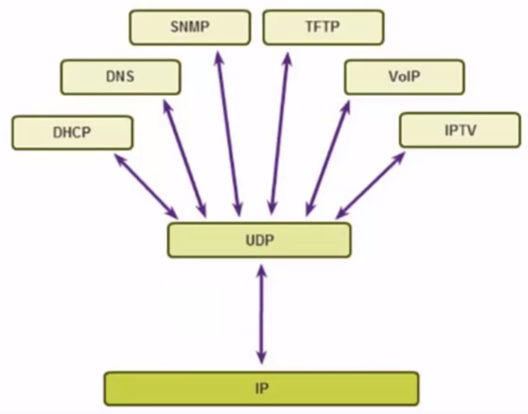
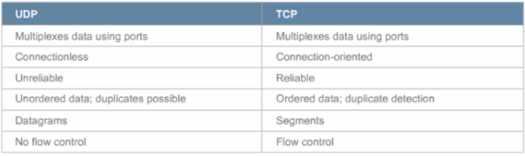
Transport Layer Protocol > UDP
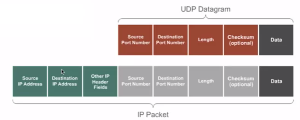
UDP Header Fields
UDP Use Cases
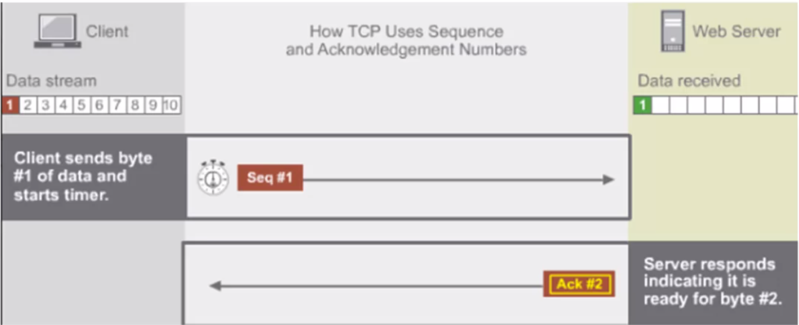
Transport Layer Protocol > TCP
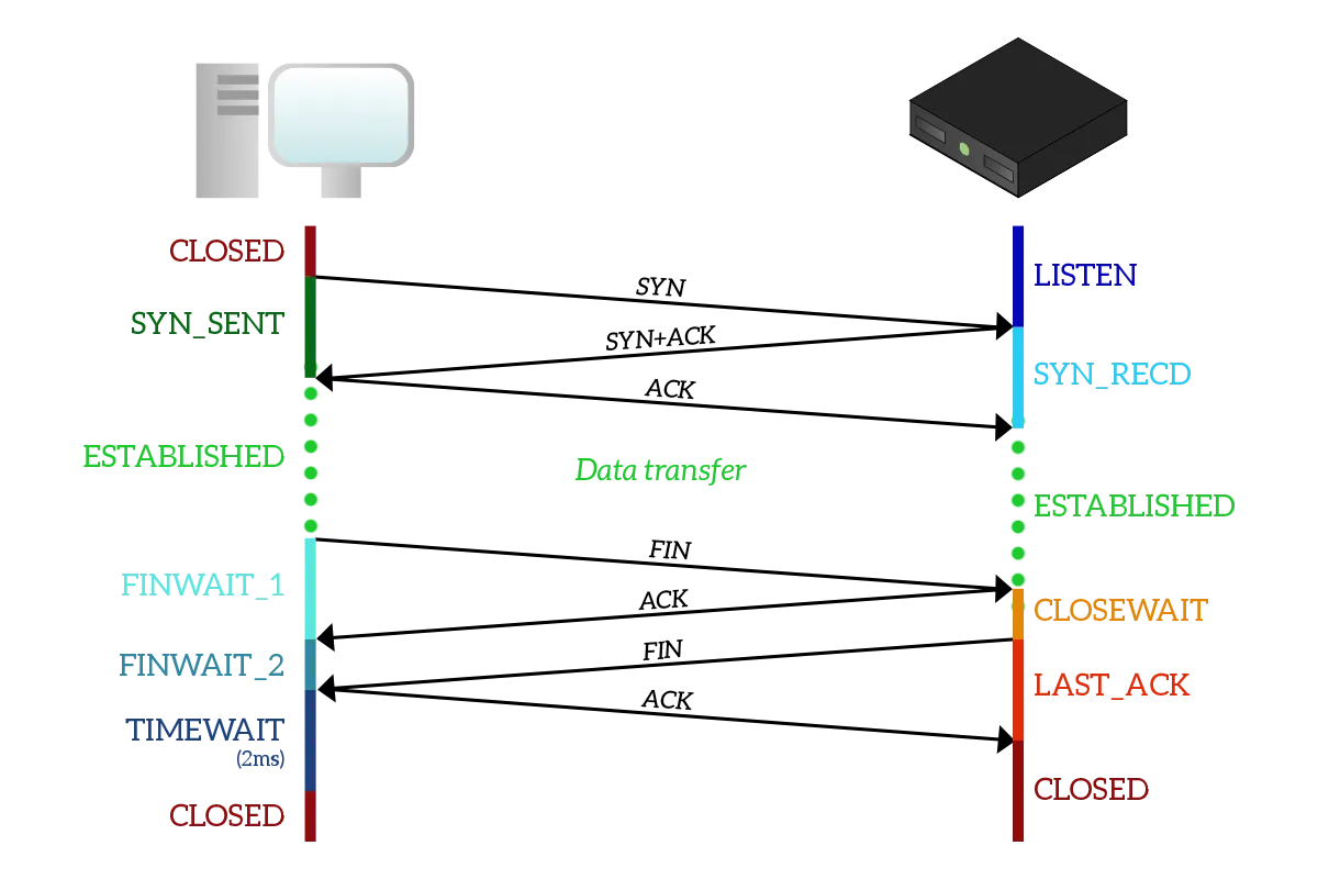
Transport Layer Protocol > TCP in Action
UDP vs TCP
Application Protocols – HTTP
- Developed by Tim Berners-Lee.
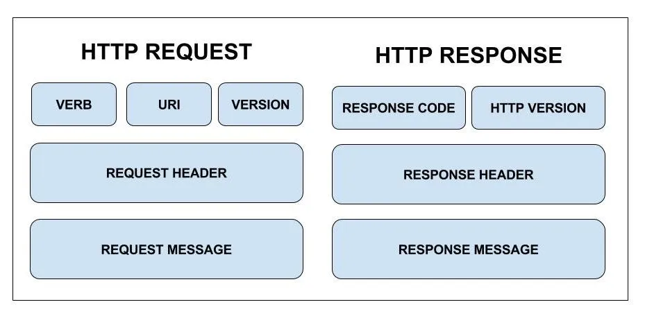
- HTTP works on a request response cycle; where the client returns a response.
- It is made of 3 blocks known as the start-line header and body.
Not secure.
Application Protocols – HTTPS
- Designed to increase privacy on the internet.
- Make use of SSL certificates.
- It is secured and encrypted.
TCP/IP Layer 5 – Application Layer Overview
DNS and DHCP
DNS
Domain Name System or DNS translates domains names into IP addresses.
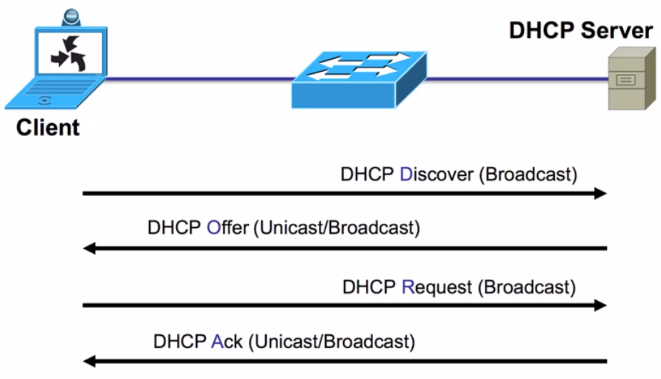
DHCP
Syslog Message Logging Protocol
Syslog is standard for message logging. It allows separation of the software that generates messages, the system that stores them, and the software that report and analyze them. Each message is labeled with a facility code, indicating the software type generating the message, and assigned a severity label.
Used for:
- System management
- Security auditing
General informational analysis, and debugging messages
Used to convey event notification messages. Provides a message format that allows vendor specific extensions to be provided in a structured way.
Syslog utilizes three layers
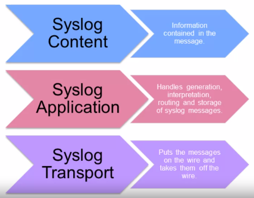
Functions are performed at each conceptual layer:
- An “originator” generates syslog content to be carried in a message. (Router, server, switch, network device, etc.)
- A “collector” gathers syslog content for further analysis. — Syslog Server.
- A “relay” forwards messages, accepting messages from originators or other relays and sending them to collectors or other relays. — Syslog forwarder.
- A “transport sender” passes syslog messages to a specific transport protocol. — the most common transport protocol is UDP, defined in RFC5426.
- A “transport receiver” takes syslog messages from a specific transport protocol.
Syslog messages components
- The information provided by the originator of a syslog message includes the facility code and the severity level.
- The syslog software adds information to the information header before passing the entry to the syslog receiver:
- Originator process ID
- a timestamp
- the hostname or IP address of the device.
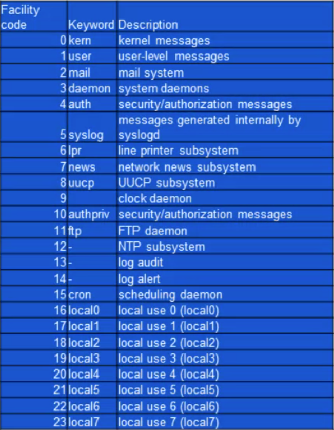
Facility codes
- The facility value indicates which machine process created the message. The Syslog protocol was originally written on BSD Unix, so Facilities reflect the names of the UNIX processes and daemons.
If you’re receiving messages from a UNIX system, consider using the User Facility as your first choice. Local0 through Local7 aren’t used by UNIX and are traditionally used by networking equipment. Cisco routers, for examples, use Local6 or Local7.
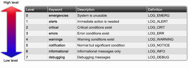
Syslog Severity Levels
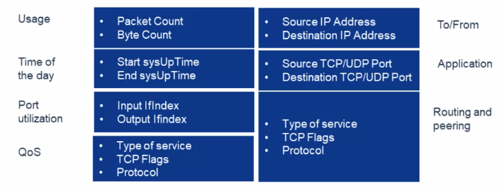
Flows and Network Analysis
What information is gathered in flows?
Port Mirroring and Promiscuous Mode
Port mirroring
- Sends a copy of network packets traversing on one switch port (or an entire VLAN) to a network monitoring connection on another switch port.
- Port mirroring on a Cisco Systems switch is generally referred to as Switched Port Analyzer (SPAN) or Remote Switched Port analyzer (RSPAN).
- Other vendors have different names for it, such as Roving Analysis Port (RAP) on 3COM switches.
- This data is used to analyze and debug data or diagnose errors on a network.
- Helps administrators keep a close eye on network performance and alerts them when problems occur.
- It can be used to mirror either inbound or outbound traffic (or both) on one or various interfaces.
Promiscuous Mode Network Interface Card (NIC)
In computer networking, promiscuous mode (often shortened to “promisc mode” or “promisc. mode”) is a mode for a wired network interface controller (NIC) or wireless network interface controller (WNIC) that causes the controller o pass all traffic it receives to the Central Processing Unit (CPU) rather than passing only frames that the controller is intended to receive.
Firewalls, Intrusion Detection and Intrusion Prevention Systems
Next Generation Firewalls – Overview
What is a NGFW?
- A NGFW is a part of the third generation of firewall technology. Combines traditional firewall with other network device filtering functionalities.
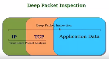
- Application firewall using in-line deep packet inspection (DPI)
- Intrusion prevention system (IPS).
- Other techniques might also be employed, such as TLS/SSL encrypted traffic inspection, website filtering.
NGFW vs. Traditional Firewall
- Inspection over the data payload of network packets.
- NGFW provides the intelligence to distinguish business applications and non-business applications and attacks.
Traditional firewalls don’t have the fine-grained intelligence to distinguish one kind of Web traffic from another, and enforce business policies, so it’s either all or nothing.
NGFW and the OSI Model
The firewall itself must be able to monitor traffic from layers 2 through 7 and make a determination as to what type of traffic is being sent and received.
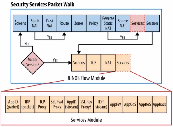
NGFW Packet Flow Example and NGFW Comparisons
Flow of Traffic Between Ingress and Egress Interfaces on a NGFW
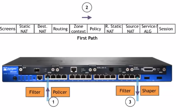
Flow of Packets Through the Firewall
NGFW Comparisons:
- Many firewalls vendors offer next-generation firewalls, but they argue over whose technique is the best.
- A NGFW is application-aware. Unlike traditional stateful firewalls, which deal in ports and protocols, NGFW drill into traffic to identify the application transversing the network.
- With current trends pushing applications into the public cloud or to be outsourced to SaaS provides, a higher level of granularity is needed to ensure that the proper data is coming into the enterprise network.
Examples of NGFW
Cisco Systems
Cisco Systems have announced plans to add new levels of application visibility into its Adaptive Security Appliance (ASA), as part of its new SecureX security architecture.
Palo Alto Networks
Says it was the first vendor to deliver NGFW and the first to replace port-based traffic classification with application awareness. The company’s products are based on a classification engine known as App-ID. App-ID identifies applications using several techniques, including decryption, detection, decoding, signatures, and heuristics.
Juniper Networks
They use a suite of software products, known as AppSecure, to deliver NGFW capabilities to its SRX Services Gateway. The application-aware component, known as AppTrack, provides visibility into the network based on Juniper’s signature database as well as custom application signatures created by enterprise administrators.
NGFW other vendors:
- McAfee
- Meraki MX Firewalls
- Barracuda
- Sonic Wall
- Fortinet Fortigate
- Check Point
- WatchGuard
Open Source NGFW:
pfSense
It is a free and powerful open source firewall used mainly for FreeBSD servers. It is based on stateful packet filtering. Furthermore, it has a wide range of features that are normally only found in very expensive firewalls.
ClearOS
It is a powerful firewall that provides us the tools we need to run a network, and also gives us the option to scale up as and when required. It is a modular operating system that runs in a virtual environment or on some dedicated hardware in the home, office etc.
VyOS
It is open source and completely free, and based on Debian GNU/Linux. It can run on both physical and virtual platforms. Not only that, but it provides a firewall, VPN functionality and software based network routing. Likewise, it also supports paravirtual drivers and integration packages for virtual platforms. Unlike OpenWRT or pfSense, VyOS provides support for advanced routing features such as dynamic routing protocols and command line interfaces.
IPCop
It is an open source Linux Firewall which is secure, user-friendly, stable and easily configurable. It provides an easily understandable Web Interface to manage the firewall. Likewise, it is most suitable for small businesses and local PCs.
IDS/IPS
Classification of IDS
- Signature based: Analyzes content of each packet at layer 7 with a set of predefined signatures.
- Anomaly based: It monitors network traffic and compares it against an established baseline for normal use and classifying it as either normal or anomalous.
Types of IDS
- Host based IDS (HIDS): Anti-threat applications such as firewalls, antivirus software and spyware-detection programs are installed on every network computer that has two-way access to the outside.
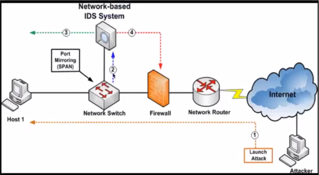
- Network based IDS (NIDS): Anti-threat software is installed only at specific points, such as servers that interface between the outside environment and the network segment to be protected.
NIDS
- Appliance: IBM RealSecure Server Sensor and Cisco IDS 4200 series
- Software: Sensor software installed on server and placed in network to monitor network traffic, such as Snort.
IDS Location on Network
Hybrid IDS Implementation
- Combines the features of HIDS and NIDS
- Gains flexibility and increases security
- Combining IDS sensors locations: put sensors on network segments and network hosts and can report attacks aimed at particular segments or the entire network.
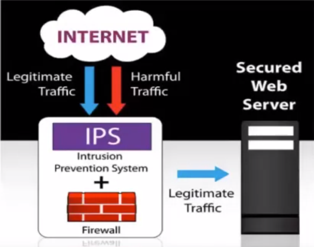
What is an IPS?
- Network security/threat prevention technology.
- Examines network traffic flows to detect and prevent vulnerability exploits.
Often sits directly behind the firewall.
How does the attack affect me?
- Vulnerability exploits usually come in the form of malicious inputs to a target application or service.
- The attackers use those exploits to interrupt and gain control of an application or machine.
- Once successful exploit, the attacker can disable the target application (DoS).
- Also, can potentially access to all the rights and permissions available to the compromised application.
Prevention?
- The IPS is placed inline (in the direct communication path between source and destination), actively analyzing and taking automated actions on all traffic flows that enter the network. Specifically, these actions include:
- Sending an alarm to the admin (as would be seen in an IDS)
- Dropping the malicious packets
- Blocking traffic from the source address
- Resetting the connection
Signature-based detection
It is based on a dictionary of uniquely identifiable patterns (or signatures) in the code of each exploit. As an exploit is discovered, its signature is recorded and stored in a continuously growing dictionary of signatures. Signatures detection for IPS breaks down into two types:
- Exploit-facing signatures identify individual exploits by triggering on the unique patterns of a particular exploit attempt. The IPS can identify specific exploits by finding a match with an exploit-facing signatures in the traffic.
- Vulnerability-facing signatures are broader signatures that target the underlying vulnerability in the system that is being targeted. These signatures allow networks to be protected from variants of an exploit that may not have been directly observed in the wild, but also raise the risk of false positive.
Statistical anomaly detection
- Takes samples of network traffic at random and compares them to a pre-calculated baseline performance level. When the sample of network traffic activity is outside the parameters of baseline performance, the IPS takes action to handle the situation.
- IPS was originally built and released as a standalone device in the mid-2000s. This, however, was in the advent of today’s implementations, which are now commonly integrated into Unified Threat Management (UTM) solutions (for small and medium size companies) and NGFWs (at the enterprise level).
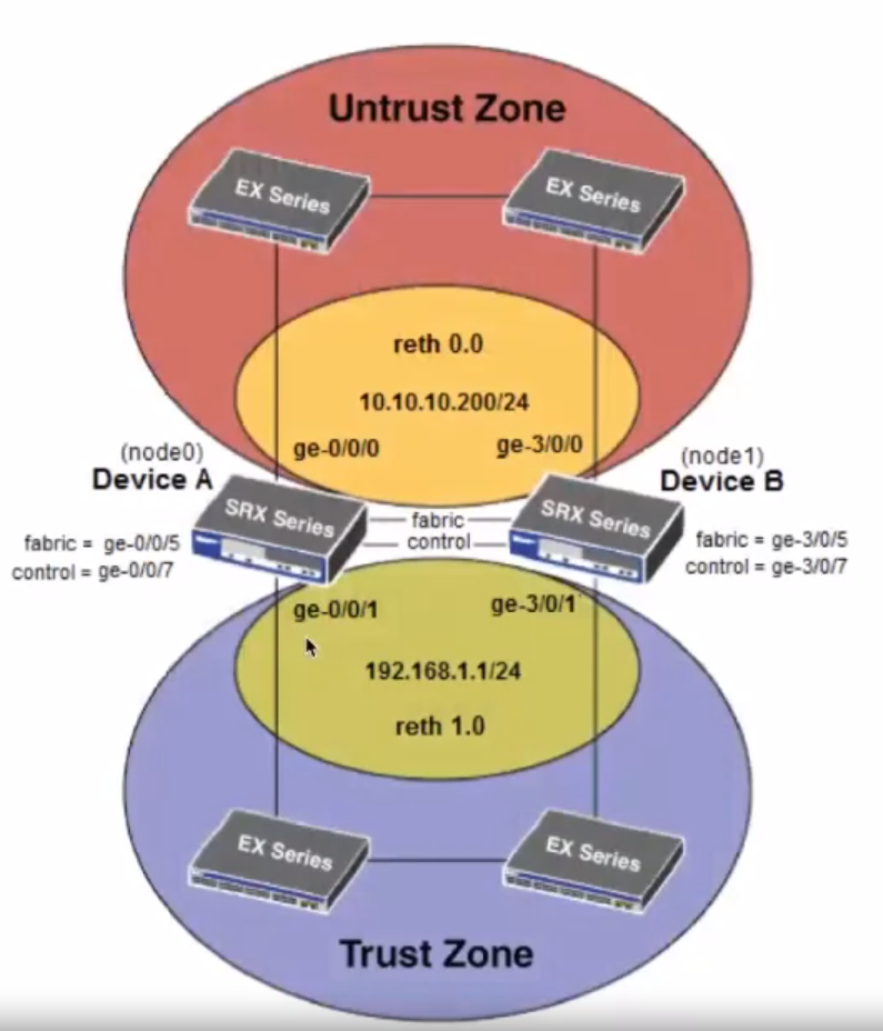
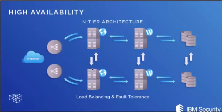
High Availability and Clustering
What is HA?
- In information technology, high availability (HA) refers to a system or component that is continuously operational for a desirably long length of time. Availability can be measured relative to “100% operational” or “never failing”.
- HA architecture is an approach of defining the components, modules, or implementation of services of a system which ensures optimal operational performance, even at times of high loads.
- Although there are no fixed rules of implementing HA systems, there are generally a few good practices that one must follow so that you gain most out of the least resources.
Requirements for creating an HA cluster?
- Hosts in a virtual server cluster must have access to the same shared storage, and they must have identical network configurations.
- Domain name system (DNS) naming is important too: All hosts must resolve other hosts using DNS names, and if DNS isn’t set correctly, you won’t be able to configure HA settings at all.
- Same OS level.
- Connections between the primary and secondary nodes.
How HA works?
To create a highly available system, three characteristics should be present:
Redundancy:
Means that there are multiple components that can perform the same task. This eliminates the single point of failure problem by allowing a second server to take over a task if the first one goes down or becomes disabled.
Monitoring and Failover
In a highly available setup, the system needs to be able to monitor itself for failure. This means that there are regular checks to ensure that all components are working properly. Failover is the process by which a secondary component becomes primary when monitoring reveals that a primary component has failed.
NIC Teaming
It is a solution commonly employed to solve the network availability and performance challenges and has the ability to operate multiple NICs as a single interface from the perspective of the system.
NIC teaming provides:
- Protection against NIC failures
- Fault tolerance in the event of a network adapter failure.
HA on a Next-Gen FW